Check Valves: Controlling Flow Direction
As an authorized representative and distributor for Hayward Flow Control since 2001, we have witnessed the evolution of their thermoplastic check valve product line; I thought it would be nice to have an article summarizing Hayward’s check valve product offering and some basic information about applications for check valves.
What is a Check Valve?
A check valve enforces a one-way flow path in a piping system. The most common applications involve preventing the reversal of flow in a piping system where pumps or filters are installed. An example of this would be to help maintain the prime within a centrifugal pump system.
Sometimes check valves are used to maintain fluid and pressure within sections of a piping system. Check valves also help protect all piping components from excessive water hammer during pump start-up or initial filling of the pipeline. Another common application for check valves is to prevent loss of process fluid through spray nozzles once the pump is turned off; Adjustable spring tensioned Y check valves are particularly good for this application. You can also use check valves as an anti-siphon valve when the process line is below the fill level of the feed tank of a pump system; centrifugal and peristaltic pumps have no internal check valves to otherwise enforce the flow path, permitting a liquid source above the pump (on either the inlet or outlet side) flow in the wrong direction during an upset condition.
Hayward manufactures non-alloy flow control products and their check valves fall under one of the following four designs:
-
Ball check valves made of PVC, CPVC, Polypropylene and PVDF for non-viscous and clean fluids where there is at least ≥ 2 PSI of system backpressure to ensure proper operation.
-
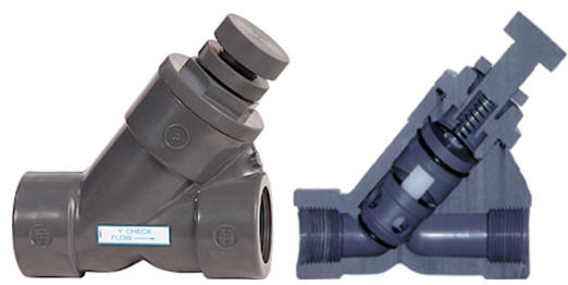
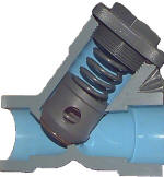
Y check valves in PVC, CPVC and PVDF used typically for dirtier and higher viscosity liquids. Designs include spring assist to adjust the cracking pressure/speed of closure.
-
Full body style swing check valves made of PVC, CPVC and Polypropylene which are used for larger piping systems; they can also be fitted with limit switches for position indication and counter weights for quicker closure.
-
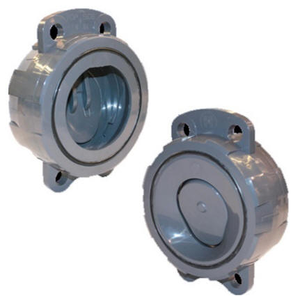
PVC Wafer check valves are another choice for larger piping systems and high flow rates, especially when there are space restrictions or when the liquid contains solids which might foul a full body style swing check valve. Optional stainless steel or Hastelloy springs assist with closure.
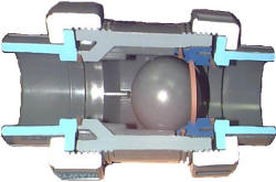
Hayward's ball check valves have a true-union body design to simplify installation and maintenance. Reliable operation occurs without any need for adjustments or settings. The line pressure moves the solid plastic ball off of the EPDM or FKM seat. When flow stops, the system back pressure pushes the ball against the seat stopping the flow. The ball is free floating, so it never seats twice in the same position, preventing uneven wear. Key features compared to competing designs are: the ball is retained with the true union nuts removed and it is safety blocked.
Ball check valves can only be used within horizontal sections of piping or vertical sections where the flow rate is upwards. If installed vertically for a downwards flow direction the ball would either never seat or always be seated.
 True union connections refer to the ability to remove the valve body
from the pipeline by only unscrewing the retaining nut on either
side of the valve body. Whether your valve has threaded, socket
(glued) or flanged connections, the true union feature leaves the
connection with the pipeline intact, simplifying repair or
replacement of the valve.
Hayward's Y check valves are available with threaded, socket, or flanged connections with or without a true-union design. The internal coil guides the valve onto the seat and a minimum backpressure of 2 PSI ensures sealing of the valve against it. Spring assisted Y check valves can be installed in any position and work well with liquids that benefit from quicker closure. For example, a spring assisted Y check valve would be a better choice for a viscous liquid than a ball check valve, especially if the system pressure is low. The Y design enables servicing in-line without the necessity of disrupting the pipeline connection or having a true union connection.
The adjustable version of the Y check valve enables the user to set the spring tension or cracking pressure within 2 ≥ 15 PSI.
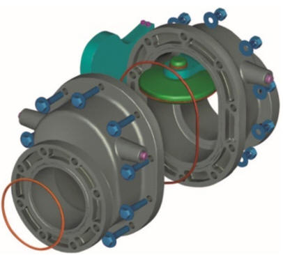
Hayward’s full body swing check valves have a truly unique and innovative design, each half of its body is identical. Therefore, if one seat wears or becomes damaged, you can reposition the valve in your pipeline after adjusting the clapper and it's like having a whole new valve!
Swing check valves are often used for slurries or liquids that would otherwise damage valve seats. Another great feature of Hayward’s full body swing check valve is the built-in o-ring flange seal, eliminating the need for separate flange gaskets. Rated for pressures up to 150 PSIG @ 70F (non-shock pressure), they only require ≥ 3 PSI for positive sealing.
Hayward’s wafer check valves are available with or without a spring assist. They are offered in 2" to 8" sizes in either PVC or CPVC materials with a full pattern design, meaning they do not require spacers or special flanges for the flapper to open fully. They are designed to be inserted between ANSI 125#, ANSI 150# and DIN PN10 pipeline flanges.
Check Valve Installation Considerations
When installed downstream of a pump, install at a distance of at least 10 pipe diameters from the pump outlet and at least 5 pipe diameters from the nearest elbow or tee.
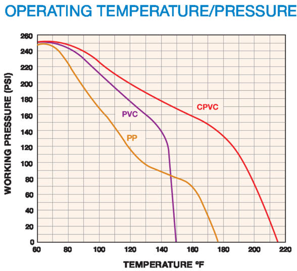
Although non-alloy valves can be used in alloy pipelines, it is good practice to try and match the valve body material with the pipeline material to ensure both chemical and thermal compatibility (alloys and non-alloys have a different coefficient of expansion, so if the liquid is extremely cold or hot intermixing alloy and non-alloy components is not recommended). Hayward does not recommend their valves for use with liquids <34F. Non-alloy valves are not designed for air or other gasses. The reason for this is the failure mode; PVC and CPVC have a tendency to explode whereas when used with liquids the failure mode is controlled or tends to form a crack rather than sending shrapnel flying everywhere.
Threaded connections are NPT (American standard tapered pipe threads) and it is suggested that a non-petroleum based sealant such as PTFE (Teflon™) plumbers tape is applied to your inlet/outlet pipe connections.
Flanged connections conform to ANSI 150# dimensions and a 1/8” thick full-face gasket having a durometer rating between 50 and 70 is required for proper sealing for models that do not have an integral flange o-ring.
 Water
Hammer
This term is used to describe the shockwave of near instantaneous pressure applied to piping components due to a fast-acting valve or suddenly stopping a pump.
To minimize the water hammer effect, size your piping such that the liquid velocity is <8 FPS (<5 FPS is ideal). Reducing the rate of dead-heading flow by slowing down a pump before it is shut off or closing valves slower are the best ways to minimize such shock. This means spring assisted check valves might not be suitable for higher velocity applications.
Hayward has a handy water hammer calculator online at https://www.haywardflowcontrol.com/en_us/water-hammer-calculator. When we look at a valve rated for 150 PSIG @ 70F non-shock pressure, that means the maximum working pressure of 150 PSI includes whatever the water hammer effect might add to the system, so the actual maximum allowable working pressure (MAWP) will be less when you leave room to accommodate water hammer. Using the Hayward water hammer calculator, the maximum line pressure is only 118 PSI for a 4” pipeline if your flow rate is 50 GPM, because the resulting potential water hammer effect could add an additional 32 PSI (thus maxing out at 150 PSI). When the flow rate (velocity) and temperature increase, the maximum working pressure decreases for a given size valve.
If you are not sure which check valve is most appropriate for your application, send us an inquiry, we typically reply quickly, certainly within 24 hours!
Additional Resources
-
Download Hayward’s complete Engineering Product Guide for additional selection criteria, such as flow coefficient values, water hammer calculations and other technical formulas.
Additional Resources (PDF files)


 Y
Check Valves