Comparison of Standard Ball Valves to Control (V-Notch) Ball Valves
call us at 908.362.9981 for immediate assistance
All valves are used to control flow or pressure in some manner; ball valves are commonplace throughout industrial piping systems and we offer a comprehensive line of ball valves in both alloy and non-alloy materials. However, there is a distinct design difference between a “standard” ball valve which control flow direction or on/off and ball valves designed for precise flow control. The distinction is in the ease of repeatable, fine control possible with ball valves modified for flow throttling compared to standard designs that are not designed to be applied that way. There are many other types of control valves, including gate, globe and needle valves. They each have their pros/cons depending upon the liquid and application characteristics. Generally, ball valves have advantages in sealing efficiency and higher flow coefficient which relates to minimizing the size of the valve and actuator required; for the purpose of this article, we’ll focus on how ball valves are modified to enable precise flow control.
Just about all valves can be used to stop and start flow and thus they are used to isolate the process fluid from other parts of the system or external environment. Examples are isolating the inlet and outlet of a filter system so you can access the element for cleaning/replacement, perhaps isolating a pump so it can be repaired and draining a vessel; these are all common examples of how industrial ball valves are used to control flow on or off.
Ball valves can also be designed with more than two ports to divert flow from one direction to another, continuing with our example above, diverting the flow from a dirty filter to a clean one so that the dirty filter can be serviced (or a pump repaired).
Ball valves typically rotate 90 degrees to change from fully opened to fully closed; ball valves that control direction of flow commonly have a 180-degree range of actuation. It is certainly possible to control flow (aka throttle flow) by positioning the valve ball only partially open. The types of applications where throttling is typically applied involve non-positive displacement pumps, usually centrifugal pumps and atmospheric or gas pressurized systems as throttling results in less flow passing through the valve the further it is closed.
Throttling flow with a ball valve doesn’t work with a positive displacement pump system because the flow rate is based upon the pumps RPM, throttling would only increase the pressure drop across the valve and would have no effect on the flow rate of the pump. To control flow with positive displacement pumps you need to control the pump shaft speed, use multiple valves to divert unwanted flow, or most commonly, incorporate a pressure regulating valve into your system.
While it is possible to throttle flow with a standard ball valve, it does not enable precise and repeatable flow control. You could measure your flow, carefully adjust the valve to the desired flow rate and lock it in-place (or remove the handle). That is tedious, especially if you need to vary the flow rate or actuate the valve often. Whether this is actually feasible depends upon the flow rate accuracy and repeatability required for your application.
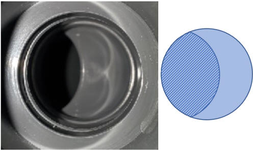
Simply put, with a standard ball valve design the percentage that the valve is opened does not correspond to the percentage of flow throttling. This is due to the elliptical shaped opening of a partially opened ball valve as illustrated by the shaded area below and the amount it changes across the 90-degree span of actuation.

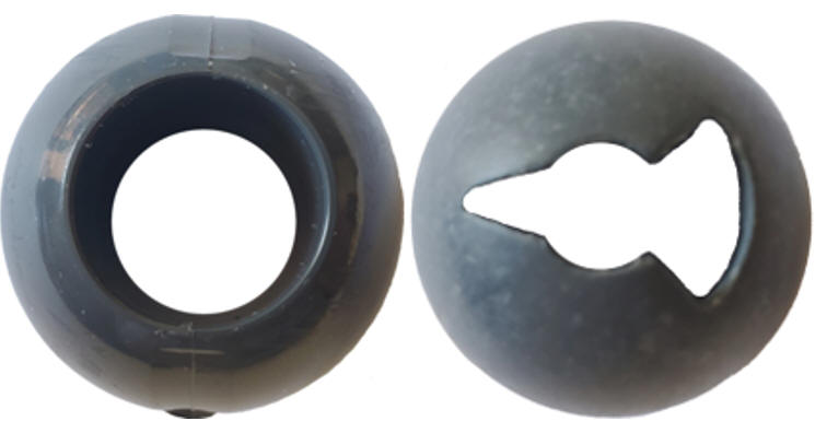
To ensure the degree of valve actuation corresponds with the degree of flow throttling, the ball opening is modified from a circle to an opening that resembles a “keyhole” pattern, commonly referred to as a V notch or V port ball valve.
Following is a side-by-side picture of a standard ball and a ball modified for flow control, note that with the modified version the open area starts off much smaller, increasing as it is further actuated; the keyhole shape improves the linearity of flow control across the 90-degree actuation range.

Flow Coefficient
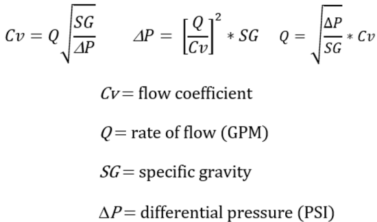
Abbreviated Cv, flow coefficient is a
measure of resistance to flow and it is based upon the volume of water at 60°F
resulting in a pressure drop of 1 PSI. The flow coefficient formula takes
into account the specific gravity of the liquid. The formula can be
rewritten to solve for differential pressure or flow rate. Thus:
-
Knowing your targeted flow rate and differential pressure determine the Cv required
-
Determine the ΔP based upon your flow rate and existing Cv
-
Calculate the maximum flow rate for a desired ΔP and Cv
Depending upon your situation, you can use these formulas to ascertain if your valve Cv is high enough to satisfy your targeted maximum differential pressure at the maximum flow rate.

Since the ball for control valves is modified compared to a standard ball valve, the determination of the valve size required is slightly different. Essentially what you want to do is to select a valve size that has a flow coefficient value (Cv) 20% higher than the required Cv of your system. You want to choose the smallest valve for the targeted Cv otherwise the operational range of your actuator will be limited; this is why there are different V notch shapes.
In summary, the Cv value represents the restriction of flow across a system or component, the higher the Cv, the less the restriction and corresponding pressure drop will be. Once you establish a tolerance for the acceptable pressure drop in your system, you can select a corresponding control valve per the aforementioned guidelines above.
Different slots for different requirements
The shape of the hole used to throttle flow corresponding to the percentage of actuation, i.e., ½ closed equates ½ flow, can vary from the “keyhole” shape. Narrower V notches and rectangular slitted openings will also provide a linear flow characteristic.

A standard ball valve having a round hole has the highest Cv value and smaller openings have a lower Cv value. The smaller V notch openings are reserved for lower flow rate applications otherwise the risk for cavitation due to excessive velocity across the opening increases. The “trick” is to select a V notch size corresponding with at least 120% of the targeted Cv while also considering the free passage required to reduce the chance of clogging. This is particularly important for slurries and liquids containing solids; while a modified ball valve design will seal better for these types of liquids, they are also more susceptible to clogging.
The valve datasheet will provide the Cv based upon the valve size and percentage of throttling for each slotted ball design offered.
Actuation
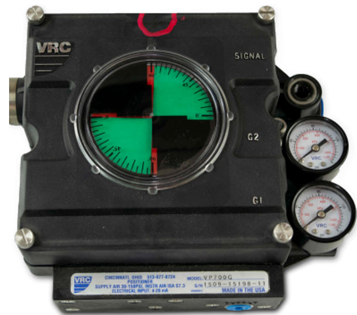
It is difficult to determine the percentage opened when operating the valve manually. Sure, if you need ½ flow you can more-or-less move the operating handle into the 45-degree position easily; but if you require it positioned at the 15% opened or some other iteration it’s difficult to position it in the same spot with repeatable accuracy. This is why control valves used for varying percentages of throttling or for applications which require frequent actuation benefit from control via a valve actuator with positioner. Valve actuators with positioners can be electrically or pneumatically driven to precisely position the percentage that the valve is rotated and thus you can program the actuator to one or more pre-set conditions to ensure repeatability. Valve actuators will also actuate quicker then manual positioning, maximizing the Cv. It is recommended to choose an oversized valve actuator to maximize the precision of the valve’s positioner.

Our ball valve and control valve product line include valves made from PVC, CPVC, brass, steel, stainless steel and other alloys. Our website https://factory-direct-valves.comom provides links to one-, two- and three-piece valve designs as well as to valve actuators and positioners. As always, our 31+ years of application experience and product knowledge is just a phone call or email away. Our web-based inquiry forms are valve specific to streamline the selection process but we are just as happy to have a discussion with you about your specific application, please remember us the next time you have a ball valve application!


